
Resolving The Build Before Groundbreaking. Zero Field Clashes.
Multi-disciplinary clash resolution, parametric 3D federated modeling, and structural-to-MEP reconciliation eliminating costly site redesigns across Ethiopian commercial and institutional projects.
Subterranean conduit clashes, structural beam core re-drilling, and HVAC duct conflicts compound rapidly once concrete is poured. Our Virtual Design & Construction unit executes digital fabrication models down to rebars, anchor bolts, and MEP branch penetrations — ensuring total spatial reconciliation prior to ground mobilization in Addis Ababa.
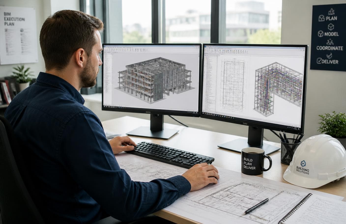
Fabrication-ready concrete, rebar & MEP shop components.
Pre-pour Navisworks & Revit hard/soft spatial interferences cleared.
Measured decrease in slab coring and beam sleeve modifications.
Terrestrial LiDAR 3D point cloud field verification.
Structured digital twin asset dossier for institutional facilities.
Integrated Coordination Deliverables
Multi-Discipline Federated Modeling
Architectural intent, reinforced concrete frames, structural steel connections, and MEP distribution synthesized into a single-source coordinate model before site groundbreaking.
Automated MEP Clash Matrix
Algorithmic collision detection in Autodesk Navisworks identifying interferences between post-tensioned tendons, gravity drainage falls, and HVAC ducts before rebar is tied.
3D Laser Scanning & As-Built Verification
High-resolution terrestrial LiDAR scanning captures as-cast column plumbness, floor levelness, and sleeve alignments, overlaying variances directly against engineering models.
Shop & Rebar Detailing Dossiers
Computer-generated bar bending schedules, sleeve layout templates, and steel connection details extracted directly from the federated model with zero manual drafting error.
5-Phase BIM Coordination Protocol
Existing Condition & Topographic Survey
High-accuracy topographic survey, property boundary registration, and existing underground utility mapping establishing true project datum elevations.
Multi-Trade Model Federation (LOD 350)
Consolidation of structural framing, architectural partitions, and MEP riser pathways into a unified coordinate system across all building levels.
Automated Clash Matrix & Spatial Resolution
Comprehensive collision detection rulesets executed weekly with structural and MEP discipline leads to resolve conflicts before steel is bent or concrete poured.
Pre-Pour Shop Drawing Generation
Extraction of dimensioned shop drawings, sleeve cutouts, embedded plates, and bar schedules stamped with exact site coordinates for field teams.
As-Built Laser Scan & Asset Dossier Handover
Progressive post-pour LiDAR scans verifying as-built positions against the design model, culminating in an audited digital asset dossier for building facility management.
QA & Spatial Compliance Matrix
| Discipline Interface | Geometric Baseline | Verification Protocol | Standard | Status |
|---|---|---|---|---|
| Structural RC vs. MEP Riser Ducts | ±5.0mm Spatial Clearance | Automated 3D Navisworks Collision Envelope | ISO 19650 / EBCS-2 | 100% RECONCILED |
| Cast-in Slab Sleeve Openings | Laser-Verified Spatial Datum | Total Station Laser Overlay Pre-Pour Inspection | DIN 18202 Class 3 | PASSED (0 ERROR) |
| Rebar Bending Schedule Detailing | Zero Field Cutting / Bending | Factory Rebar Fabrication & 3D Model Interlock | BS 8666 / ASTM A615 | CERTIFIED LOD 400 |
| Post-Tension Tendon Anchorages | ±2.0mm Profile Elevation | Volumetric Rebar Clash Simulation | PTI M10.2 / EBCS-2 | VERIFIED PRE-STRESS |
| Curtain Wall Anchors & Embeds | ±1.5mm Edge Deviation | Terrestrial LiDAR Point Cloud Deflection Heatmap | AAMA 501 / EN 13830 | SUB-MM MATCH |
Planning a Complex Multi-Disciplinary Build? Have Your Drawings Clash-Tested.
Submit your architectural, structural, and MEP CAD or BIM models. Our Addis Ababa engineering team runs a comprehensive spatial collision assessment to identify hidden field clashes and cost traps before concrete is scheduled.